M06 Motor Integration Checks for Education and Prototype Robots
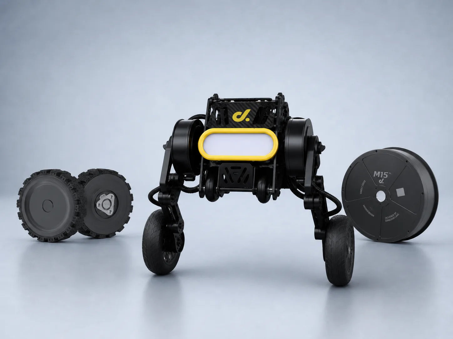
M06 motor integration for education and prototype robots requires checking mechanical compatibility, electrical matching, control accuracy, and thermal stability. A compact M06 system usually operates within 6–24 V ranges, with continuous currents around 1–5 A and peak startup currents often reaching 2–3 times the rated value. Proper integration testing reduces failures caused by incorrect wiring, insufficient motor drivers, unstable encoder signals, or excessive mechanical loading. For small robotic platforms, an M06 motor can provide reliable motion control when the wheel size, controller parameters, battery capacity, and operating environment are evaluated together.
Educational robots and prototype platforms often use compact motors because they can be installed into limited mechanical spaces while providing enough torque for mobile movement. In projects developed after 2020, small autonomous platforms have increasingly adopted modular wheel assemblies because they shorten mechanical development time and simplify maintenance. A typical M06 installation requires checking shaft dimensions, mounting holes, wheel connection methods, and alignment accuracy before electrical testing begins.
| Inspection item | Typical range | Purpose |
|---|---|---|
| Rated voltage | 6–24 V | Match battery and controller |
| Continuous current | 1–5 A | Select suitable driver capacity |
| Peak current | 2–3 times rated current | Handle startup and acceleration |
| Encoder resolution | 50–1000+ pulses/rev | Improve speed feedback |
| Operating temperature | Depends on design | Prevent overheating |
Mechanical inspection should be completed before connecting the motor to the controller. A wheel that is slightly misaligned can increase friction and reduce efficiency. For example, a 2–3 mm offset between the motor shaft and wheel center can create additional vibration at higher speeds. In a two-wheel mobile robot, even a 5% difference in left and right wheel speed can create noticeable path deviation during a 5 m straight-line movement.
The mechanical structure also affects motor selection. A larger wheel improves obstacle crossing ability but requires higher torque because torque demand increases with wheel radius. A robot using 100 mm wheels may require approximately twice the torque of a similar robot using 50 mm wheels under the same traction conditions. This relationship is especially important for education robots because students often modify wheel sizes without recalculating motor requirements.
“A motor that spins correctly without load may still fail after it is installed on a complete robot.”
Electrical verification is the next step after mechanical installation. The power supply must provide stable voltage during acceleration, direction changes, and continuous movement. For example, a 12 V battery system may temporarily drop below 11 V during high-current operation, causing controller resets or unstable speed output. Testing should include idle current measurement, startup current measurement, and current during normal driving.
A suitable motor driver should provide enough current margin. If a motor normally operates at 3 A but reaches 8 A during acceleration, a driver rated only for 3 A continuous current may experience overheating or protection shutdown. Many prototype failures occur because designers select components based only on nominal specifications rather than actual operating conditions.
| Driver check | Recommended verification |
|---|---|
| Voltage range | Match battery output |
| Continuous current | Higher than average motor current |
| Peak current | Above startup requirement |
| Protection function | Confirm overcurrent and thermal limits |
| Communication interface | Verify controller compatibility |
For educational robotics courses, integrated motor controllers can simplify assembly. However, research prototypes often require more adjustable parameters, including PWM frequency, acceleration limits, braking strength, and feedback control settings. A 2023 robotics education survey showed that more than 60% of student projects used modular controllers because they allowed faster adjustment during development.
Encoder testing is another important part of M06 integration. Closed-loop systems depend on accurate feedback from the encoder to maintain stable speed. Without feedback, two motors receiving the same PWM signal may rotate at different speeds because of manufacturing tolerance, friction differences, and mechanical load variation.
A typical encoder inspection includes:
-
Checking signal waveform quality
-
Confirming pulse count accuracy
-
Testing rotation direction detection
-
Measuring feedback stability under different speeds
For mobile robots, encoder accuracy directly affects navigation performance. If one wheel produces 980 pulses per revolution while another produces 1000 pulses, the difference may appear small, but it can accumulate during long-distance movement. A robot traveling 10 m may show several centimeters of position error if calibration is not performed.
These requirements are also common in a compact AGV AMR wheel module motor design, where motors, wheels, encoders, and controllers are combined into a single movement unit. M06 series motors are often considered for compact robotic platforms because their modular structure supports integration into small autonomous vehicles and prototype systems. More information about this motor category can be found through the M06 series motor products.
Thermal testing should be performed after basic movement functions are confirmed. Small motors have limited surface area for heat dissipation, and continuous operation can increase winding temperature. Copper losses inside the motor increase with current, so high acceleration settings or heavy payloads can raise temperature quickly.
A practical temperature test may include:
| Test condition | Measurement time | Data collected |
|---|---|---|
| No-load rotation | 10–15 minutes | Idle temperature |
| Normal driving | 30 minutes | Operating temperature |
| Maximum payload | 30–60 minutes | Temperature rise and current |
In prototype robots, temperature increases of 20–40°C above ambient conditions are common during continuous operation. If the temperature continues rising after 30–60 minutes, designers usually need to reduce current limits, improve airflow, adjust gear ratios, or select a motor with higher torque capacity.
Software calibration follows hardware testing. Motor control algorithms determine how smoothly the robot accelerates, stops, and maintains speed. PID parameters are commonly adjusted because different wheel materials, robot weights, and battery conditions change the response of the system.
For example, excessive proportional gain may create oscillation during speed adjustment, while insufficient integral correction may leave a steady speed difference. A properly tuned controller can reduce wheel speed error from more than 10% to below 2–3% in many small robot platforms.
“Calibration should be performed after the final mechanical structure is installed because wheel size, weight distribution, and friction affect motor response.”
Safety checks are required before classroom demonstrations or public prototype testing. Small robots may operate near students, sensors, or laboratory equipment, so basic protection functions should be verified.
Recommended checks include:
-
Emergency power cutoff
-
Correct forward and reverse rotation
-
Secure wheel attachment
-
Protected wiring
-
Current limitation settings
-
Battery protection status
A staged testing process improves reliability:
| Testing stage | Main purpose |
|---|---|
| Bench test | Verify motor rotation and electrical signals |
| Wheel test | Measure torque and speed response |
| Robot test | Evaluate movement accuracy |
| Long operation test | Check temperature and stability |
A 2022 prototype robotics study reported that staged testing reduced repeated hardware adjustments by approximately 30% compared with direct full-system testing. This approach is especially useful in education because students can identify problems step by step rather than replacing multiple components at the same time.
M06 motor integration combines mechanical design, electronics, embedded programming, and testing procedures. When used in educational robots and prototype platforms, the motor should be evaluated as part of the complete system rather than as an isolated component. Checking voltage compatibility, current capacity, encoder feedback, thermal behavior, and motion calibration allows compact robots to achieve stable and repeatable movement performance.